


Linear guides: how they work and how to choose them for industrial applications
LINEAR MOTION TECHNOLOGY • BOSCH REXROTH • CREATX
Linear guides: how they work and how to choose them for industrial applications
The controlled movement of a worktable, machining head or handling assembly also depends on the system that supports and guides it. Linear guides perform this role: they allow movement along a defined direction and carry the application loads, contributing to the accuracy and rigidity of the assembly.
Selection involves more than rail length or runner block size. The load, its position, the resulting moments, required accuracy, mounting conditions and operating environment all matter. A guide must be assessed as part of the complete mechanism, together with the supporting structure and drive system.
In this article, we explain how linear guides work, which types are available and what information is needed for selection. We also discuss Bosch Rexroth solutions to help you match guide characteristics to your application requirements.
Already have a linear guide installed on your machine?
To help identify it, prepare the codes marked on the rail and runner block, clear photographs and information about the application. External dimensions alone do not confirm the compatibility of a replacement.
Contents
- What linear guides are and how they work
- Types of linear guides: ball rails, roller rails and linear bushings
- Where linear guides are used in industrial automation
- How to choose a guide: loads, moments, accuracy and rigidity
- Key considerations for mounting, lubrication and protection
- Bosch Rexroth linear guides: information needed for selection
1. What linear guides are and how they work
Linear guides are mechanical assemblies that support and guide a component along a straight path. Depending on their design, they use a profiled rail and runner blocks, or guide shafts and linear bushings.
How movement is achieved
In rolling-element guides, balls or rollers move between the raceways of the rail and runner block. In recirculating designs, they travel through a circuit inside the runner block, allowing movement along the rail. Linear ball bushings use a similar principle to guide movement along shafts.
Rolling contact reduces friction compared with sliding guidance. However, the behaviour of the assembly also depends on guide type, preload, seals, lubrication and mounting quality.
Guidance and drive systems perform different roles
The guide supports the moving assembly and constrains unwanted movement. The force required for travel is supplied by a drive system, such as a ball screw, toothed belt, cylinder or linear motor. The two systems must be selected and integrated together.
Application example
In a positioning table, the guides support the table and workpiece, while the drive system produces movement. Overall accuracy depends on the complete assembly: guides, structure, transmission, measurement and control.
2. Types of linear guides: ball rails, roller rails and linear bushings
Linear guides differ in their raceway geometry, rolling elements and the way they carry loads. Common industrial solutions include profiled rail guides with balls or rollers and shaft guidance using linear ball bushings.
Profiled ball rail guides
These assemblies use balls that recirculate inside the runner block and roll along the rail raceways. They are used in positioning systems, automation and machinery, where selection balances load capacity, rigidity, accuracy and dimensions.
Roller rail guides
These guides use rollers instead of balls. Their contact geometry generally provides greater rigidity and load capacity than ball guides of comparable dimensions. They may be suitable for applications involving high loads or strict limits on assembly deflection.
Guide shafts and linear ball bushings
Linear bushings travel along cylindrical shafts and can be installed in dedicated housings. Selection depends on shaft diameter, support arrangement, distance between supports and bushing configuration. A continuously supported shaft behaves differently from one supported only at its ends.
Selection considers the complete assembly
Compare more than component dimensions or price. Check loads, moments, required rigidity, available space and mounting conditions using the technical data for the series under consideration.
3. Where linear guides are used in industrial automation
Linear guides are used wherever a component needs controlled movement in one direction while supporting a load and maintaining the geometry of the mechanism. Requirements vary by process, from handling parts to moving machining assemblies.
Handling and positioning
In pick-and-place systems, positioning tables and multi-axis assemblies, guides support the moving components. The transported mass, acceleration and distance between the load centre and the guides influence the loads and moments that must be considered.
Machine tools and assembly stations
Guides can support tables, working heads and assembly fixtures. In addition to assembly weight, selection must account for process forces, resulting moments and permissible deflection. The structure on which the guides are mounted directly affects the behaviour of the mechanism.
Packaging, inspection and format adjustments
On production lines, linear guides can be used to move packaging devices, position sensors or adjust stations during product changeovers. Movement frequency, contamination and access for lubrication are practical integration considerations.
Describe the movement, not just the component
To assess the application, prepare the moving mass, stroke, speed, acceleration, load position and an assembly sketch. This information helps determine the appropriate guide configuration.

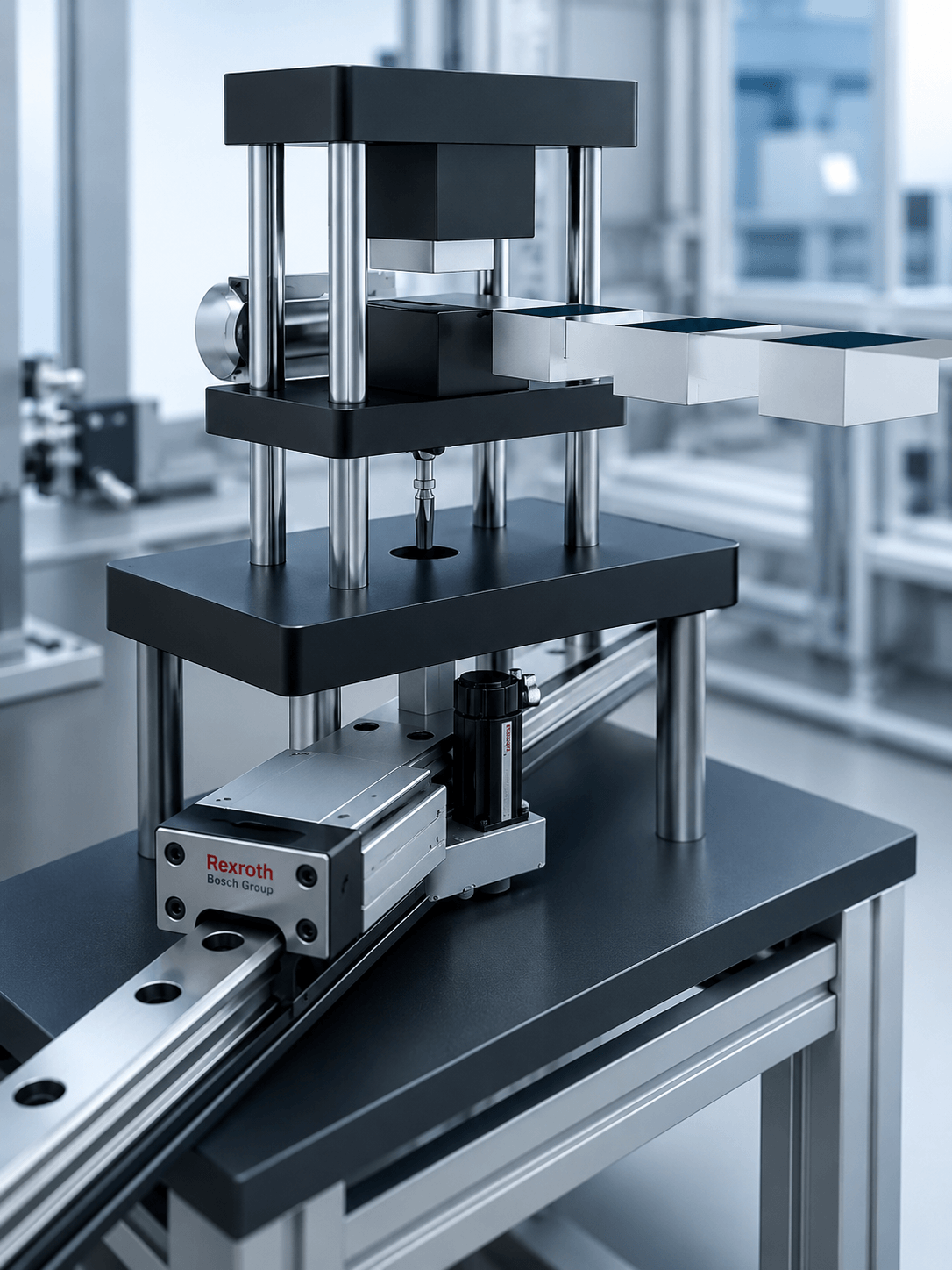
Illustration of a linear guide assembly for industrial applications.
4. How to choose a guide: loads, moments, accuracy and rigidity
Selecting linear guides starts with the loads acting on the complete assembly. Alongside the moving mass, process forces, acceleration and the position of the centre of gravity relative to the rails and runner blocks must be considered.
Loads and moments
An overhung load can generate significant moments even when its mass is low. The number of runner blocks, the spacing between them and the distance between rails affect load distribution. Verification uses the capacities and calculation method specified for the selected series.
Accuracy and rigidity
The accuracy class and preload must match the application requirements and mounting surfaces. Higher preload can increase rigidity, but it also affects resistance to movement and internal loading. Overall accuracy also depends on the structure, drive and measurement system.
Also check the operating conditions
Stroke, speed, cycle frequency, mounting orientation and operating environment influence selection. A guide's external dimensions alone are not enough to confirm its suitability for the application.
5. Key considerations for mounting, lubrication and protection
Linear guide performance also depends on installation and operating conditions. Supporting surfaces, alignment and fastening must meet the manufacturer's requirements for the configuration used.
Mounting and alignment
Mounting surfaces must be prepared and cleaned, and rails and runner blocks positioned according to the technical instructions. Flatness or parallelism deviations can introduce additional loads. The tightening sequence and bolt torques must follow the applicable documentation.
Lubrication and protection
Lubricant type, quantity and relubrication intervals depend on the product and operating conditions. Dust, chips or process fluids may require additional seals and protective measures. Access to lubrication points should be considered during the design stage.
Do not apply the same rule to every guide
Lubrication intervals and mounting requirements can vary between series and applications. Use the instructions corresponding to the exact product code.
6. Bosch Rexroth linear guides: information needed for selection
When selecting or identifying Bosch Rexroth linear guides, specify whether you are developing a new application or replacing existing components. The information required differs between these situations.
For an existing guide
Send the complete codes marked on the rail and runner block, clear photographs and relevant dimensions. Specify rail length, the number of runner blocks and which components you want to replace. Compatibility must be checked for the exact series and variant, including accuracy and preload requirements.
For a new application
- Moving mass and centre of gravity position.
- Process forces and assembly orientation.
- Stroke, speed, acceleration and cycle frequency.
- Required accuracy and permissible deflection.
- Available space, environmental conditions and an application sketch.
With this information, the CreatX team can assess your enquiry and help identify components or evaluate a suitable configuration.
Conclusion
Linear guides must be selected with the complete mechanism in mind. Loads, moments, structural rigidity and mounting conditions are just as important as component dimensions. Correct identification and verification of technical data provide the foundation for integration suited to the application.
Looking for Bosch Rexroth linear guides for your application?
Send us the code of your existing component or a sketch together with your application requirements. The CreatX team can help identify products and clarify the information needed for selection and quotation.
Get support with linear guide selectionRelated posts
-
 Bosch Rexroth Linear Guides
Learn what a linear guide is, how it works and the advantages of using Bosch Rexroth linear guides in industrial...Read more
-
 Linear bearings
Discover what linear bearings are, how they work, their main types and industrial applications, as well as the key...Read more
-
 SMS Linear Axes – Compact Solutions for Linear Motion in Industrial Automation
Discover how SMS linear axes work, their main components and advantages, industrial applications, and the essential...Read more
-
 Linear Actuators: What They Are, How They Work and How to Choose the Right Solution
Discover what linear actuators are, how they work and how to choose the right solution for industrial automation....Read more
-
 Linear Axes in Industrial Automation: Applications and Integration Criteria
Discover how linear axes are used in industrial automation and the key criteria for their selection and integration:...Read more
Leave a comment